brad225
Well-known member
- Thread Author
- #1
This description and pictures will take me a while so I apologize for it dragging on for the whole story.
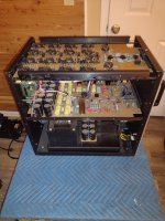
I have owned a pair of Audio Research 610t amps for 7 years. They were 10 years old when I purchased them from a dealer and were shipped directly from ARC after tube change and through testing.
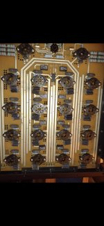
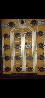
They use 8 matched pairs of 6550 power tubes, 1 6550 regulator, 16H30 regulator amplifier, 2 6L6GC driver, 1 6N1P input and 1 6H30 follower. I shake my head every time I look at it written out.
During their manufacture life ARC offered an upgrade to KT120 tubes that were more stable as they ran at lower a voltage and increased the watts per amp to 840, not that I possibly need that. The upgrade for that is actually rather simple, assuming you know what you are doing.
In this case my EE friend Phil that worked in Bell Labs for years.
He has built and rebuilt every piece of equipment he has ever owned. Built numerous crossovers for speakers he has created. He is extremely particular about the quality of parts he will use and tests and discards parts that don't match with in very small tolerances.
This description is from notes I have made and I claim no knowledge of electronics. I will do my best to describe it properly.
Last summer I talked to him about doing the upgrade to KT120 tubes as 6550 are less stable in this amp and are getting harder to find. ARC could no longer provide enough matching pair that would meet their standards last time I wanted to re-tube one amp.
We have traded woodwork for electrical work and he said he would do it.
He had a speaker build project last summer and fall and I had spine surgery so that postponed moving the 2 180lbs beasts from my second floor listening room to his home. They have now been there for a couple weeks and he is making great progress.
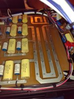
The upgrade has been pushed to the end of the line as one repair and the decision to replace many old out of spec resistors, capacitors and relays along with some parts I will describe as I describe the process.
I have owned a pair of Audio Research 610t amps for 7 years. They were 10 years old when I purchased them from a dealer and were shipped directly from ARC after tube change and through testing.
They use 8 matched pairs of 6550 power tubes, 1 6550 regulator, 16H30 regulator amplifier, 2 6L6GC driver, 1 6N1P input and 1 6H30 follower. I shake my head every time I look at it written out.
During their manufacture life ARC offered an upgrade to KT120 tubes that were more stable as they ran at lower a voltage and increased the watts per amp to 840, not that I possibly need that. The upgrade for that is actually rather simple, assuming you know what you are doing.
In this case my EE friend Phil that worked in Bell Labs for years.
He has built and rebuilt every piece of equipment he has ever owned. Built numerous crossovers for speakers he has created. He is extremely particular about the quality of parts he will use and tests and discards parts that don't match with in very small tolerances.
This description is from notes I have made and I claim no knowledge of electronics. I will do my best to describe it properly.
Last summer I talked to him about doing the upgrade to KT120 tubes as 6550 are less stable in this amp and are getting harder to find. ARC could no longer provide enough matching pair that would meet their standards last time I wanted to re-tube one amp.
We have traded woodwork for electrical work and he said he would do it.
He had a speaker build project last summer and fall and I had spine surgery so that postponed moving the 2 180lbs beasts from my second floor listening room to his home. They have now been there for a couple weeks and he is making great progress.
The upgrade has been pushed to the end of the line as one repair and the decision to replace many old out of spec resistors, capacitors and relays along with some parts I will describe as I describe the process.