- Thread Author
- #1
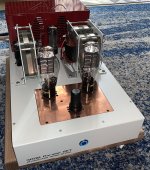
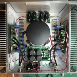
I recently finished building another DIY line stage and thought some of you might find it interesting. More info below the photos.
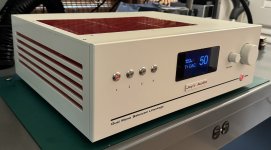
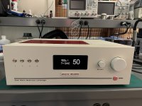
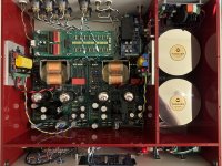
I started this project a few years ago, but I ended up building five different tube-based designs for the main line stage circuit. Some of the earlier builds worked ok, but I thought of new ideas and/or wasn't completely satisfied with the way the earlier builds sounded, so I kept going.
My current design uses a pair of 6SN7s with paralleled sections operating as a differential pair with an active current source cathode load to set the operating point, and a push/pull output transformer on the anodes. The bias is set at 14mA per tube (~7ma per triode) with a B+ of 190V.
The current sources are actually split between the two phases so that I can accurately set the DC balance, and the two tubes are coupled through a small value resistor which allows me to set the overall gain (~13db with a 220 ohm resistor). The current sources (actually sinks in this case) are implemented with cascoded BJTs with the transistor base voltages set with LM385 voltage references.
I'm using Lundahl LL1660 transformers with Nanocrystalline cores, using a 2.25+2.25:1 configuration. The paralleled triode sections with this transformer setup gives me fairly low output impedance and is working well with my DIY SET amps.
The power supply is implemented with separate oversized custom Toroidy transformers for each channel. The transformer output has tuned snubber circuits, fast-recovery schottky rectifiers and a CRCRC filter circuit, which then feeds a shut regulator for further noise reduction.
The input attenuator is implemented using a relay-switched circuit with Vishay Z-foil series resistors and Audio Note silver tantalum shunt resistors, with 256 0.5db steps. This is controlled with an Arduino processor with custom software to display on a color TFT and support an IR remote control. I've also implemented software to sequence the power and mute the output until it has warmed up. There is also a 12V trigger output to turn on my power amps after the line stage has warmed up.
Finally, there is a separate balanced to single-ended op-amp stage in parallel with the tube circuit which I use to connect my subwoofers. I've found that this circuit provides deeper and tighter bass than the tube circuit, which is somewhat limited by the output transformers capabilities.

