DIY Balanced Line Stage

JayT

Member
Joined
Feb 10, 2019
Messages
83
Location
Oregon
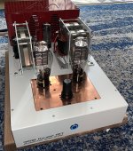
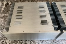
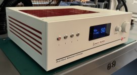
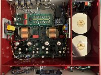
I recently finished building another DIY line stage and thought some of you might find it interesting. More info below the photos.
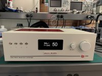
PRE3_FrontSide.jpg
PRE3_Front.jpg
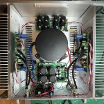
PRE3_Inside.jpg

I started this project a few years ago, but I ended up building five different tube-based designs for the main line stage circuit. Some of the earlier builds worked ok, but I thought of new ideas and/or wasn't completely satisfied with the way the earlier builds sounded, so I kept going.

My current design uses a pair of 6SN7s with paralleled sections operating as a differential pair with an active current source cathode load to set the operating point, and a push/pull output transformer on the anodes. The bias is set at 14mA per tube (~7ma per triode) with a B+ of 190V.

The current sources are actually split between the two phases so that I can accurately set the DC balance, and the two tubes are coupled through a small value resistor which allows me to set the overall gain (~13db with a 220 ohm resistor). The current sources (actually sinks in this case) are implemented with cascoded BJTs with the transistor base voltages set with LM385 voltage references.

I'm using Lundahl LL1660 transformers with Nanocrystalline cores, using a 2.25+2.25:1 configuration. The paralleled triode sections with this transformer setup gives me fairly low output impedance and is working well with my DIY SET amps.

The power supply is implemented with separate oversized custom Toroidy transformers for each channel. The transformer output has tuned snubber circuits, fast-recovery schottky rectifiers and a CRCRC filter circuit, which then feeds a shut regulator for further noise reduction.

The input attenuator is implemented using a relay-switched circuit with Vishay Z-foil series resistors and Audio Note silver tantalum shunt resistors, with 256 0.5db steps. This is controlled with an Arduino processor with custom software to display on a color TFT and support an IR remote control. I've also implemented software to sequence the power and mute the output until it has warmed up. There is also a 12V trigger output to turn on my power amps after the line stage has warmed up.

Finally, there is a separate balanced to single-ended op-amp stage in parallel with the tube circuit which I use to connect my subwoofers. I've found that this circuit provides deeper and tighter bass than the tube circuit, which is somewhat limited by the output transformers capabilities.
 
Thanks @brad225. I've posted some photos previously.

Here's a link to a post of my 300B amps.
300B_Amp2_Complete.jpg

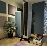
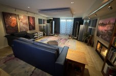
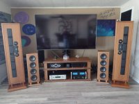
Here's a couple photos of my speakers.

LineForce_Oct23.jpg
ListeningRoomDec23.jpg

And here are a couple photos of a pair of stereo class A amps I recently finished. These utilize the F5M circuit that Nelson Pass presented at Burning Amp last year. I designed my own PCBs because I wanted a more robust power supply and some additional features (balanced inputs, speaker protection circuit), but kits are available at the DiyAudioStore and it's possible to build a stereo amp for about $600. These are an exceptional value.

I built two stereo amps to try biamping my line arrays using active crossovers.

F5M_Build3.jpg

F5T.jpg
 
Beautiful work Jay.

What drivers did you use in your line array speakers. If you don't mind.

I also use an i9 and Rendu.

These are speakers of an EE friend. I did the woodwork and he does the design and installation of electrical parts.

I sent him a text to take a look at your preamp you just posted. He builds and works on a lot of audio equipment.
Most recent for me was rebuilding my ARC 610t amps and changing them to use KT120 from 6550s.

A8AB72B8-A4E1-4B84-BE48-48E9B3DE8D65.jpeg
 
Beautiful work Jay.

What drivers did you use in your line array speakers. If you don't mind.

I also use an i9 and Rendu.

These are speakers of an EE friend. I did the woodwork and he does the design and installation of electrical parts.

I sent him a text to take a look at your preamp you just posted. He builds and works on a lot of audio equipment.
Most recent for me was rebuilding my ARC 610t amps and changing them to use KT120 from 6550s.

View attachment 33915
Those look pretty cool. Are those AMT tweeters?

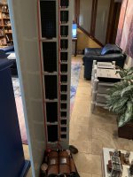
Each of my speakers has six Bohlender-Graebener NEO10s and sixteen NEO3s. The line arrays are fairly sensitive at 98db/w, and these are currently driven by my 300B SET amps.

The woofer towers are using Rythmik 12"" servo drivers with paper cones. These are driven by Rythmik HX800 amps (2x400W for each channel).

Here's a photo from behind. These are dipoles (including the woofer towers).

LF_Wire_2.jpg
 
I recently finished building another DIY line stage and thought some of you might find it interesting. More info below the photos.
View attachment 33898
View attachment 33899
View attachment 33900

I started this project a few years ago, but I ended up building five different tube-based designs for the main line stage circuit. Some of the earlier builds worked ok, but I thought of new ideas and/or wasn't completely satisfied with the way the earlier builds sounded, so I kept going.

My current design uses a pair of 6SN7s with paralleled sections operating as a differential pair with an active current source cathode load to set the operating point, and a push/pull output transformer on the anodes. The bias is set at 14mA per tube (~7ma per triode) with a B+ of 190V.

The current sources are actually split between the two phases so that I can accurately set the DC balance, and the two tubes are coupled through a small value resistor which allows me to set the overall gain (~13db with a 220 ohm resistor). The current sources (actually sinks in this case) are implemented with cascoded BJTs with the transistor base voltages set with LM385 voltage references.

I'm using Lundahl LL1660 transformers with Nanocrystalline cores, using a 2.25+2.25:1 configuration. The paralleled triode sections with this transformer setup gives me fairly low output impedance and is working well with my DIY SET amps.

The power supply is implemented with separate oversized custom Toroidy transformers for each channel. The transformer output has tuned snubber circuits, fast-recovery schottky rectifiers and a CRCRC filter circuit, which then feeds a shut regulator for further noise reduction.

The input attenuator is implemented using a relay-switched circuit with Vishay Z-foil series resistors and Audio Note silver tantalum shunt resistors, with 256 0.5db steps. This is controlled with an Arduino processor with custom software to display on a color TFT and support an IR remote control. I've also implemented software to sequence the power and mute the output until it has warmed up. There is also a 12V trigger output to turn on my power amps after the line stage has warmed up.

Finally, there is a separate balanced to single-ended op-amp stage in parallel with the tube circuit which I use to connect my subwoofers. I've found that this circuit provides deeper and tighter bass than the tube circuit, which is somewhat limited by the output transformers capabilities.
Fantastic build would love to hear it ...


Regards
 
Thanks @brad225. I've posted some photos previously.

Here's a link to a post of my 300B amps.
View attachment 33908

Here's a couple photos of my speakers.

View attachment 33909
View attachment 33910

And here are a couple photos of a pair of stereo class A amps I recently finished. These utilize the F5M circuit that Nelson Pass presented at Burning Amp last year. I designed my own PCBs because I wanted a more robust power supply and some additional features (balanced inputs, speaker protection circuit), but kits are available at the DiyAudioStore and it's possible to build a stereo amp for about $600. These are an exceptional value.

I built two stereo amps to try biamping my line arrays using active crossovers.

View attachment 33911

View attachment 33912
Fantastic setup , i guess you’re series parallel with that line array, 98db is really pretty high , great stuff ...!
 
great looking pieces of kit Jay and I assume the sound as good as they look !!
 
Fantastic setup , i guess you’re series parallel with that line array, 98db is really pretty high , great stuff ...!
Thanks. Yes, the NEO3s are connected four in series, and the four groups in parallel. The NEO10s are two groups of three in series. Sensitivity increases by 3db each time you double the number of drivers.

great looking pieces of kit Jay and I assume the sound as good as they look !!
Thanks. The speakers sound fabulous - by far the best I've owned. I've heard a few speakers at audio shows that might be a bit better, but all at six figure prices. I don't think these will ever leave my system, at least as long as I have the space for them.

The amps sound very nice, but I've heard a lot of really nice sounding amps. The 300Bs have a gorgeous midrange, but I wouldn't mind a bit more grunt in the 150Hz to 250Hz range and the high frequencies are a little on the polite side. But overall, I'm pretty happy with them. I've got several other amps I've built which have different strengths and weaknesses, and I'm sure I'll build more amps in the future.

The jury is still out on the preamp. I've only got about 50 hours on it at this point. It sounds pretty good, and it does seem to be getting better. But it could be that I'm getting more used to the sound. I'll switch back to my previous preamp build after I've put another 50-100 hours on this to see how it compares. I've got another preamp project I am working on (quite a bit more complex than this one), but I am putting this on the back burner until I finish building a new streamer/DAC.
 
My current design uses a pair of 6SN7s with paralleled sections operating as a differential pair with an active current source cathode load to set the operating point, and a push/pull output transformer on the anodes. The bias is set at 14mA per tube (~7ma per triode) with a B+ of 190V.

The current sources are actually split between the two phases so that I can accurately set the DC balance, and the two tubes are coupled through a small value resistor which allows me to set the overall gain (~13db with a 220 ohm resistor). The current sources (actually sinks in this case) are implemented with cascoded BJTs with the transistor base voltages set with LM385 voltage references.
I found that most of the time you're better off just tying the two differential halves directly together and using a single CCS. The problem is you wind up with too much gain but if you use a balanced (2 deck) shunt style gain trim control you can manage it quite well. Some sources (mostly digital) will likely need some attenuation and others may not.

The output transformers may have an issue with loading. We used to build a balanced preamp about 30 years ago that had a transformer coupled output. The transformer was designed to drive 600 Ohms but that sort of thing is rare in high end audio. Unloaded, as it would be if plugged into a balanced amp with a 50K input impedance or even 10K, the capacitance between the primary and secondary windings would act like a coupling cap bypassing the transformer, so frequency response was not flat. By loading the output with a 1K resistor we got it nice and flat with good bass.

Keep in mind the load on the transformer is reflected back to the tube(s) driving it.
Ralph - thanks for your comments and wisdom. I will try the changes you suggested when I open it up again.
 
Back
Top