Line Source Speaker Build

brad225

Active member
Joined
Apr 11, 2017
Messages
1,002
Location
Wesley Chapel, FL
I have a Electrical Engineer friend, Phil, that is a total DIY person. He has rebuilt or modified every piece of equipment he owns. The crossovers and circuits he builds are amazing.

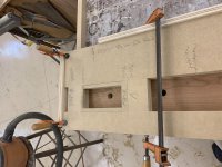
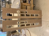
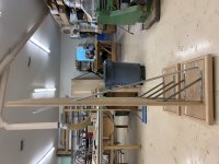
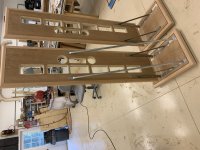
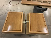
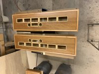
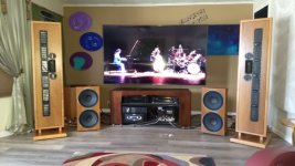
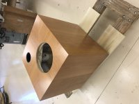
I have built boxes for other speakers he has constructed, including the sub in the left corner of this picture.

attachment.php


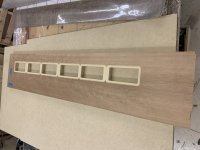
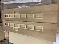
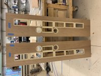
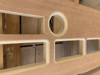
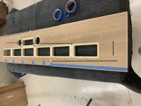
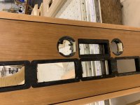
This is a picture he sent me when he had all of the drivers in and working on the crossovers.

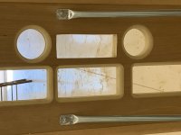
The 6 midrange drivers are designed by Bruce Thigpen (Eminent Technology). Phil has disassembled them and replaced all of the magnets and changed the circuits.
The 1 tweeter is by Mundorf and the 2 super tweeters are from a company in the Netherlands. I have forgotten the name.

I am going to break this into a number of posts as I keep losing the text when making it to long.
 

Attachments

  • image000000.jpg
    image000000.jpg
    84.1 KB · Views: 94
attachment.php


This is the finished sub before he installed the drivers. It was MDF with internal bracing.
 

Attachments

  • IMG_0892.JPG
    IMG_0892.JPG
    2.3 MB · Views: 85
Very cool Brad, like how you apparently wrapped the veneer from each side over top of sub. Yes, I listened in last Sunday, it appears Phil has gone to the Dark Side - dipoles, cardioids, lots of measurements, the whole shebang. Nice.:). RIP Bozak.
 
The line source panels were from 1 1/4" MDF. They were covered with Cherry veneer, solid Cherry on the edges and dyed black inlay between them.
The bases were from 1 /3/4" MDF.

I started by building all of the jigs I would need to make multiple openings for the different drivers. Aside from the shape they were all different depths and radius on the corners.

After I finished building the jigs I realized the cutters I planed to use for some of the different steps either didn't exist or weren't going to do the job accurately enough. With trial and painful error I managed to change my approach altering the jigs and how I used them.

I ended up with different bits in 4 separate routers and only twice picked up the wrong one and started to use it. Only once did a router bit slide out of the collet that holds it in place.
All three times it made an ugly mess. Fortunately my extensive antique restoration back ground allows me to repair all of the mistakes I make.

One under repair. This project did cause a bit of increase in wine consumption.


attachment.php
 

Attachments

  • tH5Mm3b9QTKpg03gIhvqKw.jpg
    tH5Mm3b9QTKpg03gIhvqKw.jpg
    2.5 MB · Views: 85
Very cool Brad, like how you apparently wrapped the veneer from each side over top of sub. Yes, I listened in last Sunday, it appears Phil has gone to the Dark Side - dipoles, cardioids, lots of measurements, the whole shebang. Nice.:). RIP Bozak.

Thanks
You have clearly helped pull him there AJ.
 
attachment.php

Main Jig for mid range drivers.

attachment.php


Insert to route hole through panel.


attachment.php


attachment.php


Stop block to hold insert in place. Ready to route hole through panel.
 

Attachments

  • ffJqS795QTaSkXRGMLVwwQ.jpg
    ffJqS795QTaSkXRGMLVwwQ.jpg
    2.6 MB · Views: 85
  • xGFbk+EBQ1WNPOByF7AKDw.jpg
    xGFbk+EBQ1WNPOByF7AKDw.jpg
    2.3 MB · Views: 84
  • MN9qx2s2SBeI2%u1Bpm+MA.jpg
    MN9qx2s2SBeI2%u1Bpm+MA.jpg
    2.4 MB · Views: 87
  • GRLLflv6T%qd+cwB0SpF1g.jpg
    GRLLflv6T%qd+cwB0SpF1g.jpg
    2.5 MB · Views: 80
attachment.php


Hole successfully cut through panel.


attachment.php


Recess for driver flange routed with insert removed.

Now I only needed to do it 5 more times so the drivers would fit together end to end with no extra space.

Then do another panel as a mirror image without more mistakes.
 
attachment.php


First group of 6 was a major relief.

attachment.php


I then added the tweeter openings using the same basic type of jigs.

attachment.php


I was so relieved when I had the original 1 super tweeter opening done.

The next morning Phil called and asked if I would do a second super tweeter below the tweeter. In my mind I was saying no, no, no, no I have the hard part done. The other 2 were not problem and took less time than the first 2 did.

attachment.php


The back of the midrange and super tweeter openings were rounded over as they are dipole drivers.
 

Attachments

  • BRM0POzdTWudJ6Y8RHRnoA.jpg
    BRM0POzdTWudJ6Y8RHRnoA.jpg
    2.3 MB · Views: 75
  • 64pbyBZDRzmNNg3QtI9dfA.jpg
    64pbyBZDRzmNNg3QtI9dfA.jpg
    2.4 MB · Views: 79
  • Ythf3FZTQAWjj45Vo7vzcw.jpg
    Ythf3FZTQAWjj45Vo7vzcw.jpg
    1.9 MB · Views: 75
  • TohXmfLFSWuJWQUm0GcBzw.jpg
    TohXmfLFSWuJWQUm0GcBzw.jpg
    2.1 MB · Views: 11
  • iVq40O4%QzG3CtjOyHfJ2g.jpg
    iVq40O4%QzG3CtjOyHfJ2g.jpg
    2.4 MB · Views: 69
Phil’s presentation was very interesting. It’s too bad his Bozak’s blew up after all the work he put into them. He spent thousands of hours on those things. Hard to believe there was nothing left but one coil after they blew up.

I guess I’m one that won’t totally appreciate the DIY component. When Phil mentioned he spent $7000 scouring for old parts on eBay, was exposed to serious chemicals that could affect his health in changing the magnets and an additional 520 hours of build time, I was left scratching my head. That’s the true love of the DIY guy.

I can appreciate all the work and joy of doing something yourself. That’s the fun for guys like Phil, AJ, John and others. I get it. They love building stuff for themselves and that’s awesome. It’s always fun to see what they can do.

For me, if I wanted Planar Magnetic speakers, I would probably find a gently used pair of Magnepan 20.7’s for $10K and spend the rest of the time listening to music.

To each their own I guess.
 
attachment.php


Next came the black inlay. A router with a fence on it allowed for the 1/4" wide by 1/28" deep rebate to glue it in.

attachment.php


I masked off the Cherry veneer to prevent glue being spread onto it.


attachment.php


attachment.php

My very low tech method for mitering the inlay.

attachment.php


The inlay is glued in place and held with a few pieces of painters tape until it drys.
 

Attachments

  • FKimer1GTBq5qJ9%mYqJig.jpg
    FKimer1GTBq5qJ9%mYqJig.jpg
    2.3 MB · Views: 67
  • pv8yAj6AQViQtm1ZkIrMrw.jpg
    pv8yAj6AQViQtm1ZkIrMrw.jpg
    2.1 MB · Views: 66
  • MZFDFRcKQG+OU+V+kJxevA.jpg
    MZFDFRcKQG+OU+V+kJxevA.jpg
    1.8 MB · Views: 65
  • m1hq4hwJRYO%P8Vl8CEBrw.jpg
    m1hq4hwJRYO%P8Vl8CEBrw.jpg
    2.3 MB · Views: 67
  • oCbzvQLdRZKZsobOS4U2oQ.jpg
    oCbzvQLdRZKZsobOS4U2oQ.jpg
    2 MB · Views: 66
attachment.php


attachment.php


Panels and bases with inlay and Cherry edging.
 

Attachments

  • i1d+ndKUSH25+pZ8%cBmwQ.jpg
    i1d+ndKUSH25+pZ8%cBmwQ.jpg
    2.1 MB · Views: 63
  • Y31tNoCcSvufLt2snG1Xng.jpg
    Y31tNoCcSvufLt2snG1Xng.jpg
    1.7 MB · Views: 64
attachment.php

Next was to make braces to prevent any panel movement

attachment.php


attachment.php


Phil wanted a round brace he could cover with an acoustical felt. We used 1/2" electrical conduit that I cut to length and fortunately my Emmerts Patternmakers vise flattened it with no problem. It made for very neat ends and I just bent it to the proper angles top and bottom while still in the vise.


attachment.php


attachment.php
 

Attachments

  • 6CxZ3y3iRJWHEkT1+qeR7g.jpg
    6CxZ3y3iRJWHEkT1+qeR7g.jpg
    2.1 MB · Views: 62
  • +jhFvO+aTUOKHBxCFvLWDg.jpg
    +jhFvO+aTUOKHBxCFvLWDg.jpg
    1.8 MB · Views: 61
  • mT%%tZJBRWy2BVV2NURthA.jpg
    mT%%tZJBRWy2BVV2NURthA.jpg
    2.5 MB · Views: 62
  • jUgHSbALQ22a2RYshMAJ%g.jpg
    jUgHSbALQ22a2RYshMAJ%g.jpg
    2.2 MB · Views: 64
  • HRhpB+jnSf+bfQFicuUyZw.jpg
    HRhpB+jnSf+bfQFicuUyZw.jpg
    1.3 MB · Views: 65
attachment.php


Hardware all painted black

attachment.php


attachment.php


Bases and Panels getting their lacquer finish.
 

Attachments

  • aDce5W4wRaKILdr%NkGNnA.jpg
    aDce5W4wRaKILdr%NkGNnA.jpg
    2.5 MB · Views: 59
  • 6ejG+qxzS6SYXwvtaQoj7Q.jpg
    6ejG+qxzS6SYXwvtaQoj7Q.jpg
    2.2 MB · Views: 59
  • 38N9WeydQbGcS9UXR3KWog.jpg
    38N9WeydQbGcS9UXR3KWog.jpg
    1.9 MB · Views: 60
  • Nw7Dg%fTTBmijjzIHAmgJg.jpg
    Nw7Dg%fTTBmijjzIHAmgJg.jpg
    2.3 MB · Views: 13
The back of each panel has been covered with same acoustic felt.

I will post finished pictures when I get to hear them next week.
 
brad, thats some incredible work! congratulation, really like it.
cool working place as well. what sets it above almost other hobbyrooms is that you have a ventilation system!!
i had a line source speaker not long ago (piega), they do the best imaging of all types of speaker. have fun!
 
For me, if I wanted Planar Magnetic speakers, I would probably find a gently used pair of Magnepan 20.7’s for $10K and spend the rest of the time listening to music.

To each their own I guess.
Yep. Well, of course Phil is retired. He could clearly have gotten something like the 20.7s with his budget. Haven't heard these yet, but while having some similarities, they should also sound significantly different, the Mags being true lines, Phils being essentially point sources, with a quasi line midbass section, too short to develop true cylindrical wavefronts.
Plus the voltage sensitivity will be well north of 95db, unlike the 86db/4 ohm Maggies, so effectively around 83db/watt. Not something I would drive with his McIntosh tube amp. If he did it correctly (and it sounds like he did), the cardioid bass bins would also kill the Maggie in that area, punch depth and dynamics. And finally, those Brad creation frames appear to put Maggies to shame in terms of structural rigidity, while also having a gorgeous custom finish.
Proof will be in the pudding of course, different strokes for different folks.

cheers,

AJ
 
Back
Top