November 6, 2011
Acoustics in my small audio room – Update Three
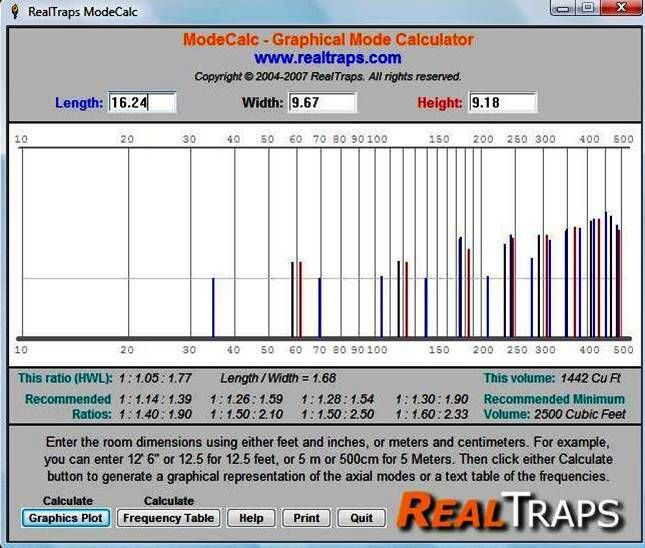
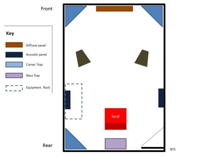
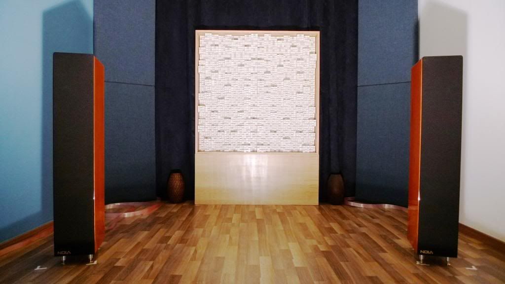
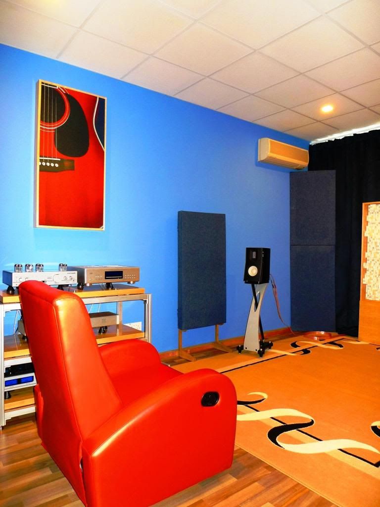
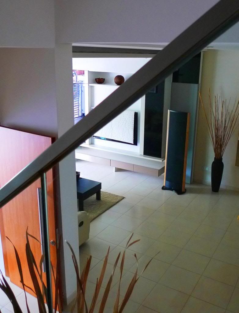
This update is a continuation of my thoughts and experiments in setting up a good listening environment within the confines of a small listening room measuring 5m x 3m x 2.8m (L,W,H). Philosophically the room design is LEDE with the speaker end being moderately diffuse (and reflective) and the listening end employing absorption.
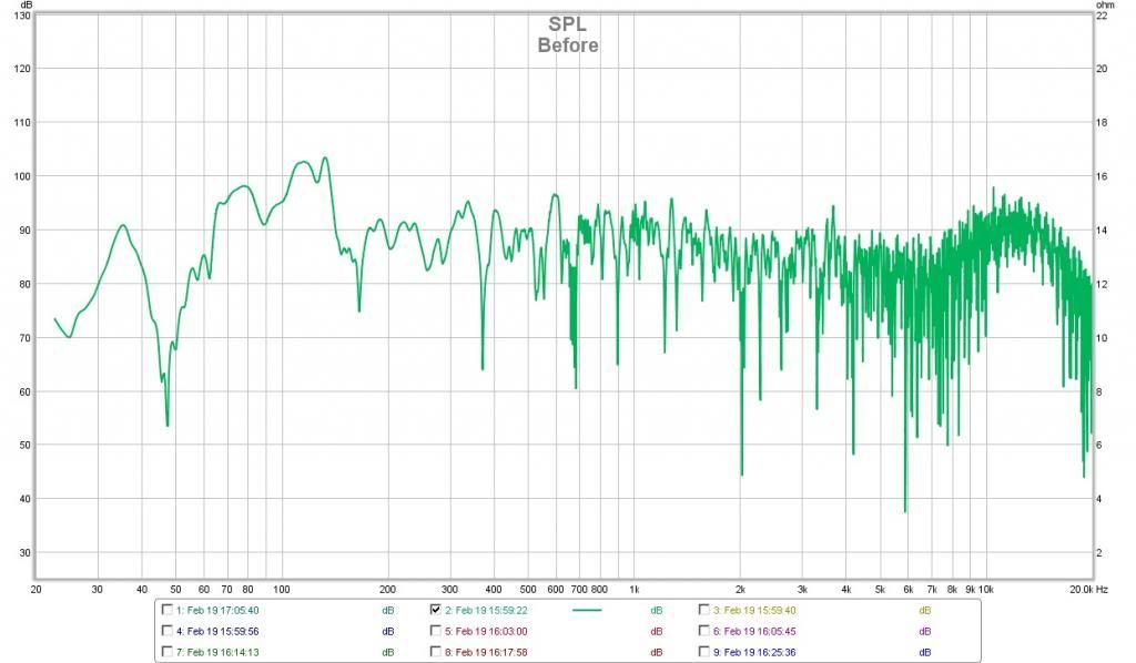
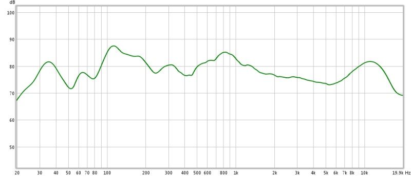
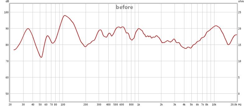
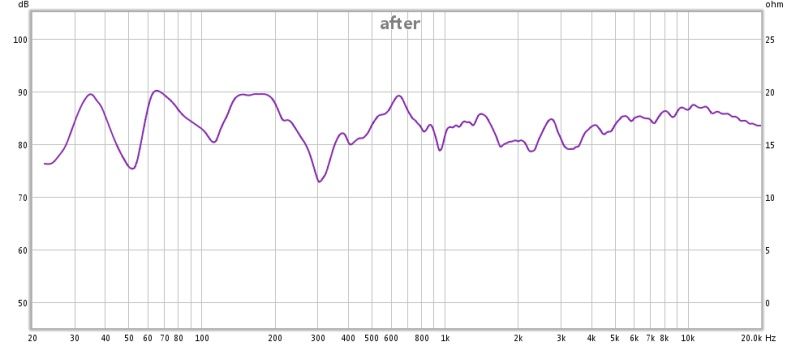
While generally pleased with the results to date which have seen giant strides in flattening frequency response, reductions in slap echo and audible improvements to the evenness and the intelligibility of the bass I have felt that more progress could be made and this update serves as a record to that end.
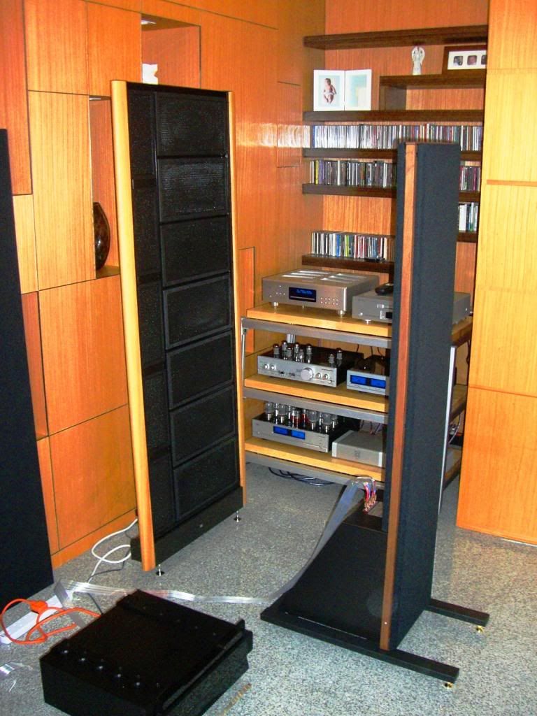
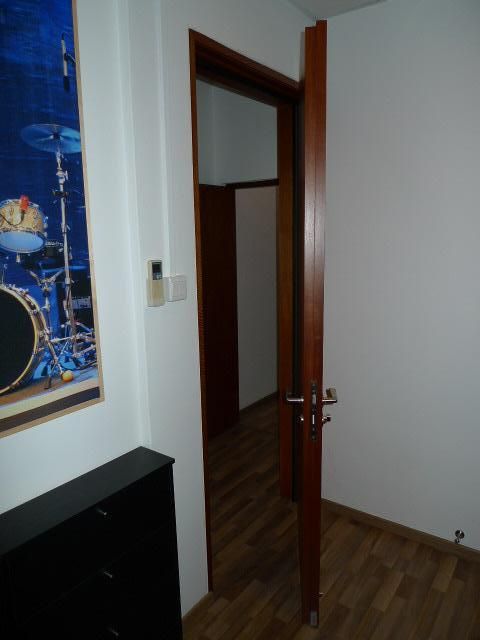
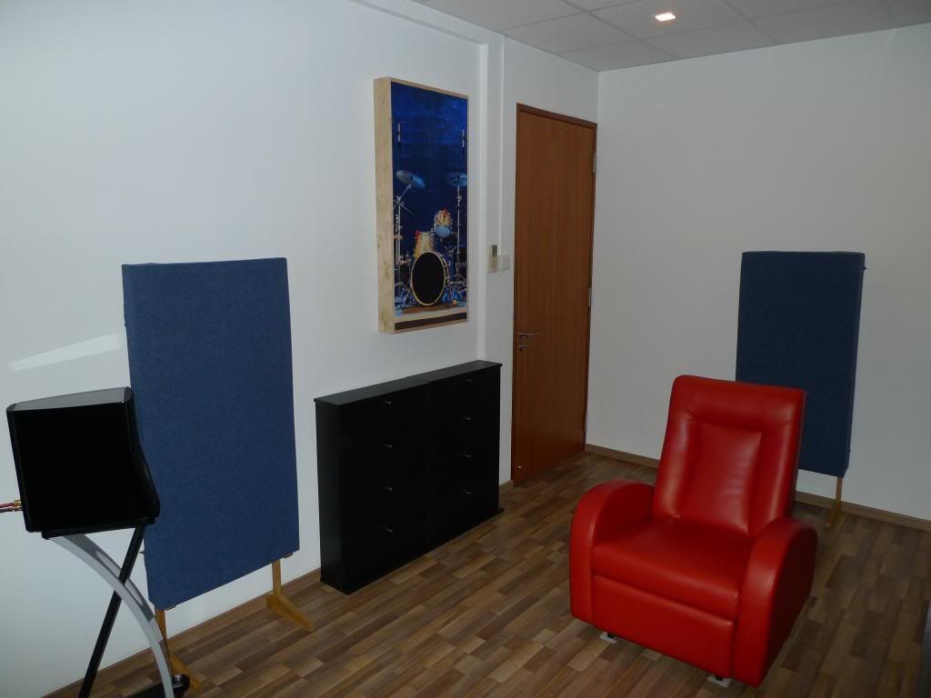
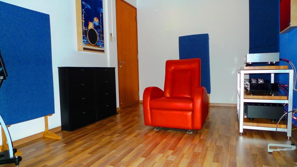
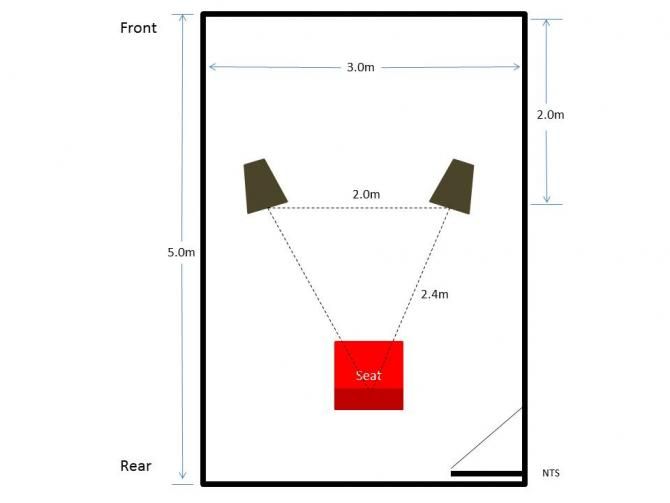
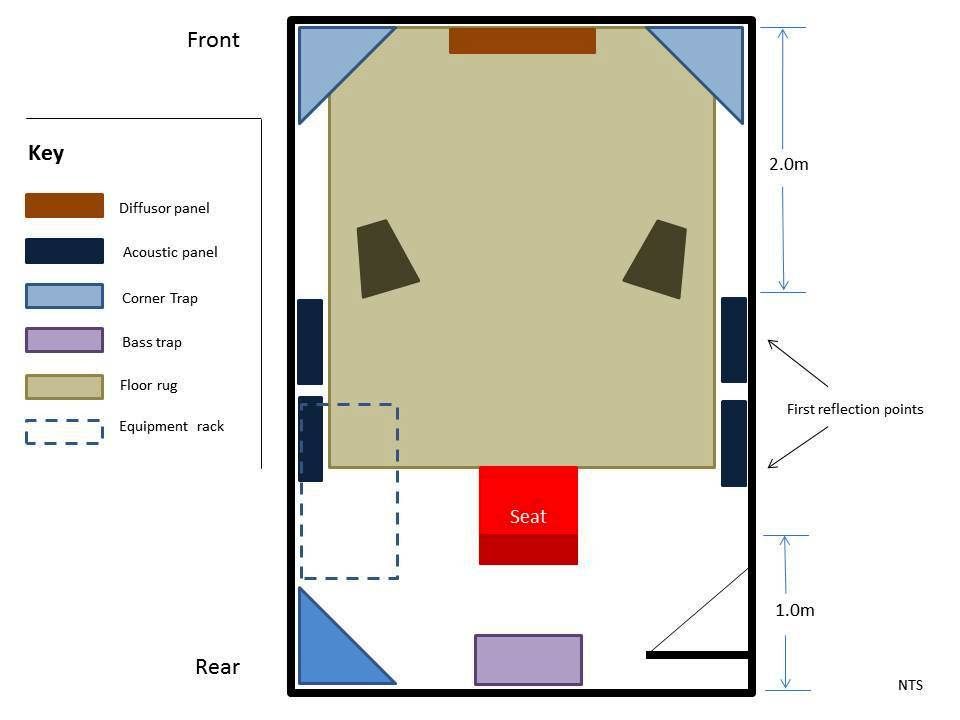
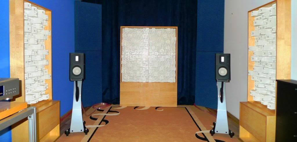
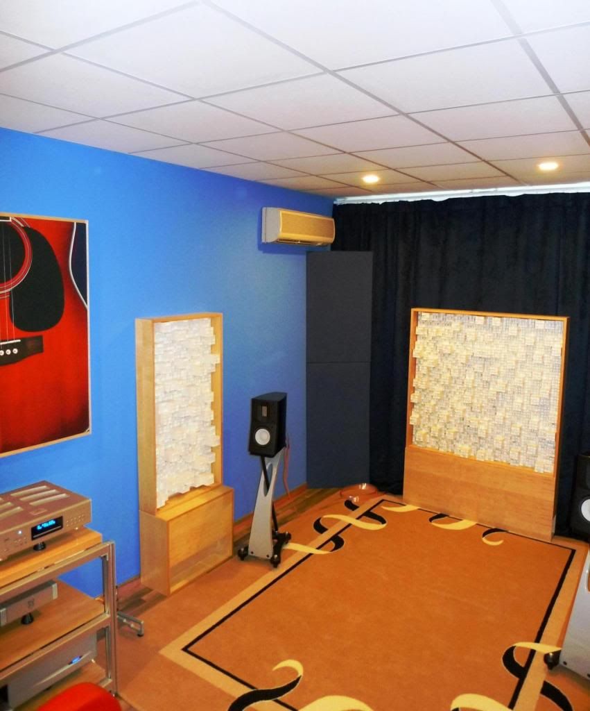
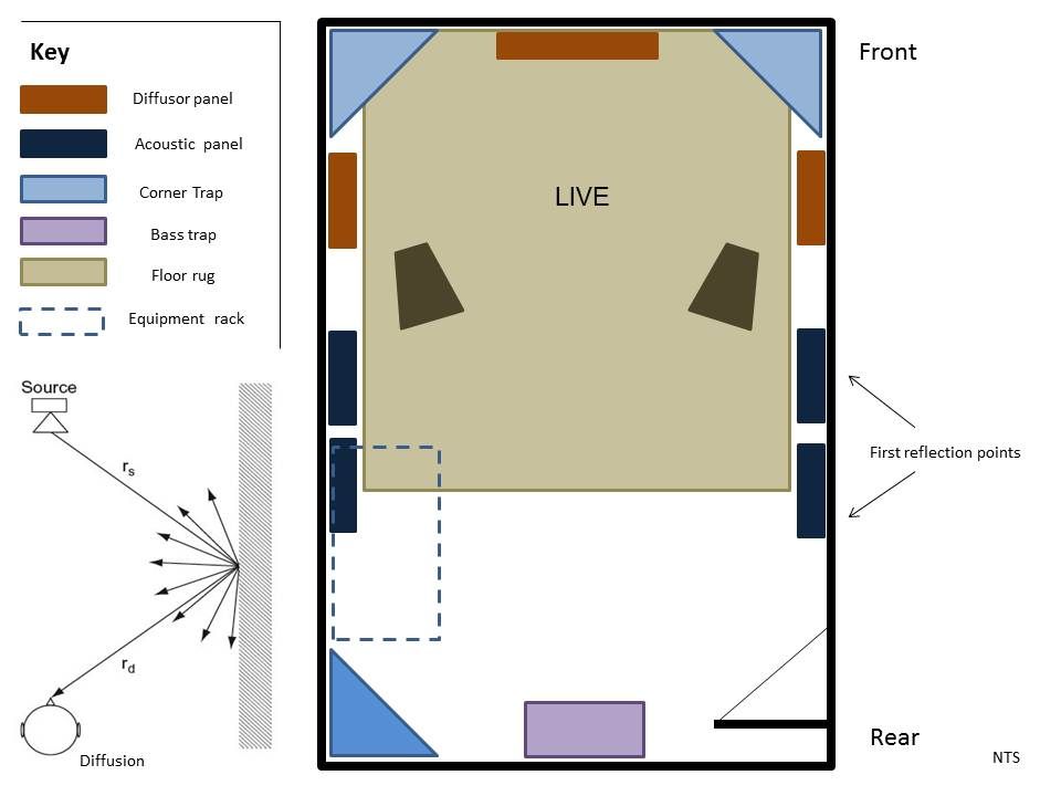
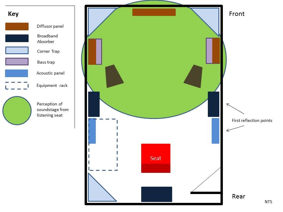
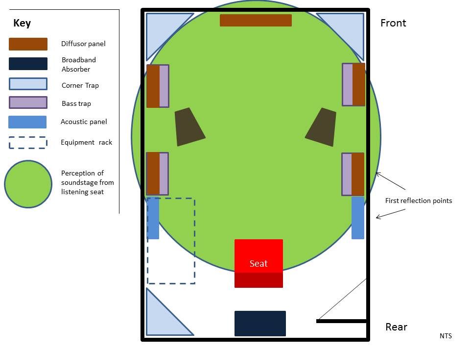
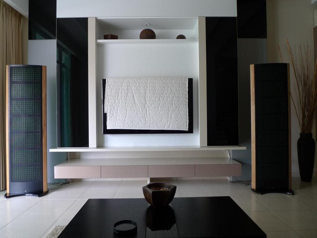
At time of writing my existing room treatment placement is shown in Figure 1 below.
REFLECTION vs. ABSORPTION AT FIRST REFLECTION POINT
My endless tinkering generated from untamed curiosity naturally led to questions on what type of treatment should be employed at the first reflection point? Note here that I am focused on the reflection point closest to each loudspeaker. A quick literature review on the topic of reflection vs. absorption vs. diffusion at the point of first reflection shows strong support for absorption but protagonists exist for reflection (no treatment at all) and diffusion. It needs to be stated for the record that my focus here is acoustic treatment for small rooms and large rooms play by very different rules.
Moreover, observations that follow should be read in conjunction with information provided in earlier updates and noting that the bass trap which resides under the diffusor will impact the sub 500Hz range.
In order to arrive at my own conclusions on the topic I embarked on a series of experiments which incorporated listening tests, LEDR tests and finally measurements.
First up was the listening tests which compared reflection (no treatment, brick, plaster and painted wall), absorption (GIK 242 panel) and diffusion (DIY 2D diffuser with bass trap base).
What follows are my observations.
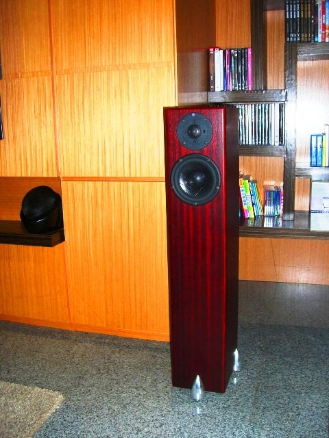
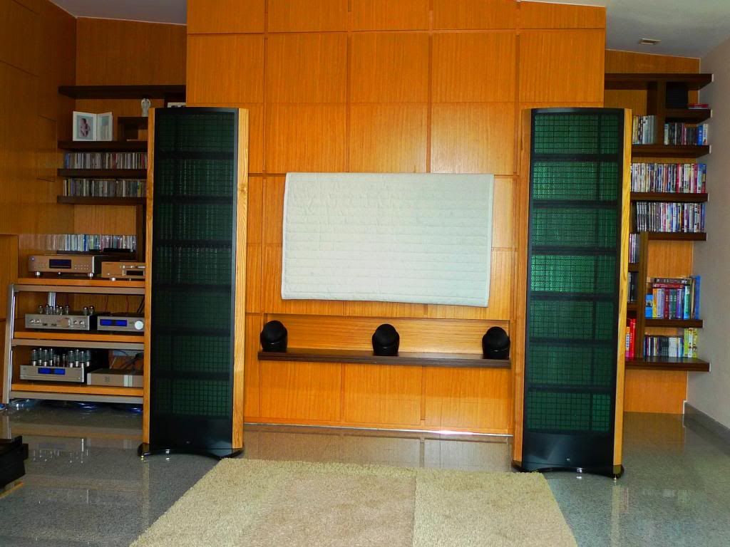
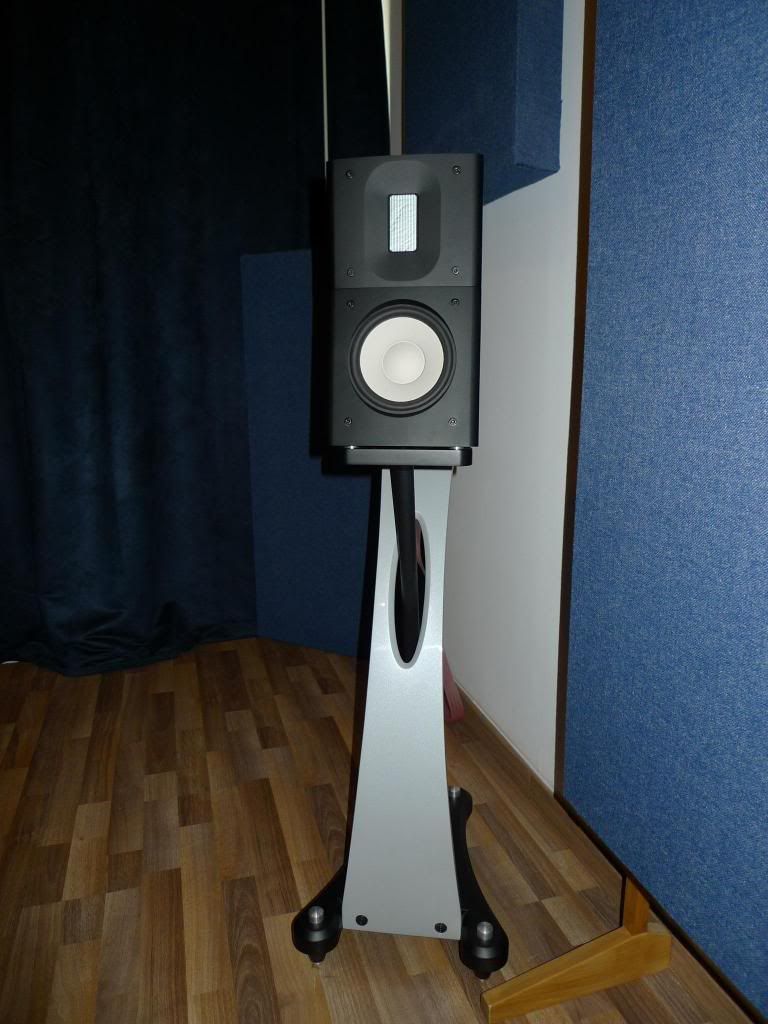
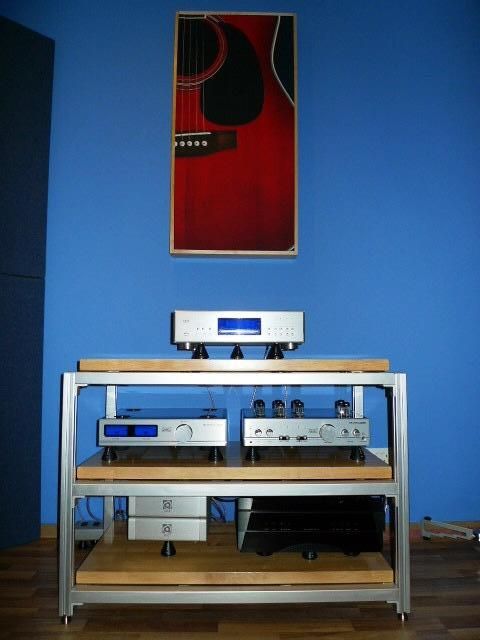
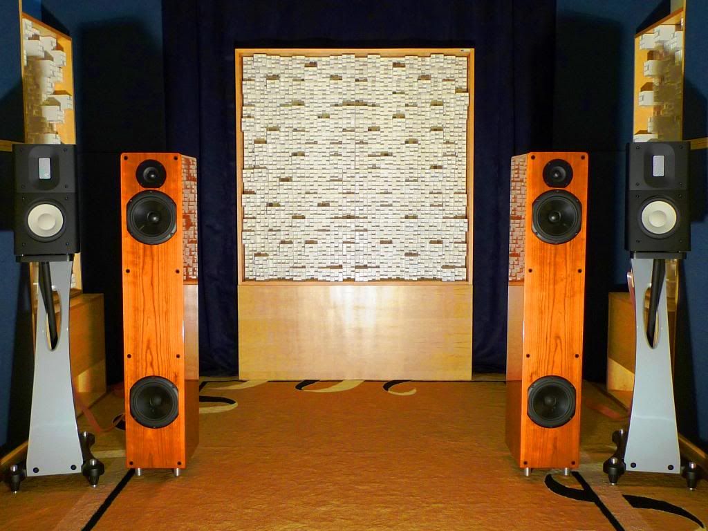
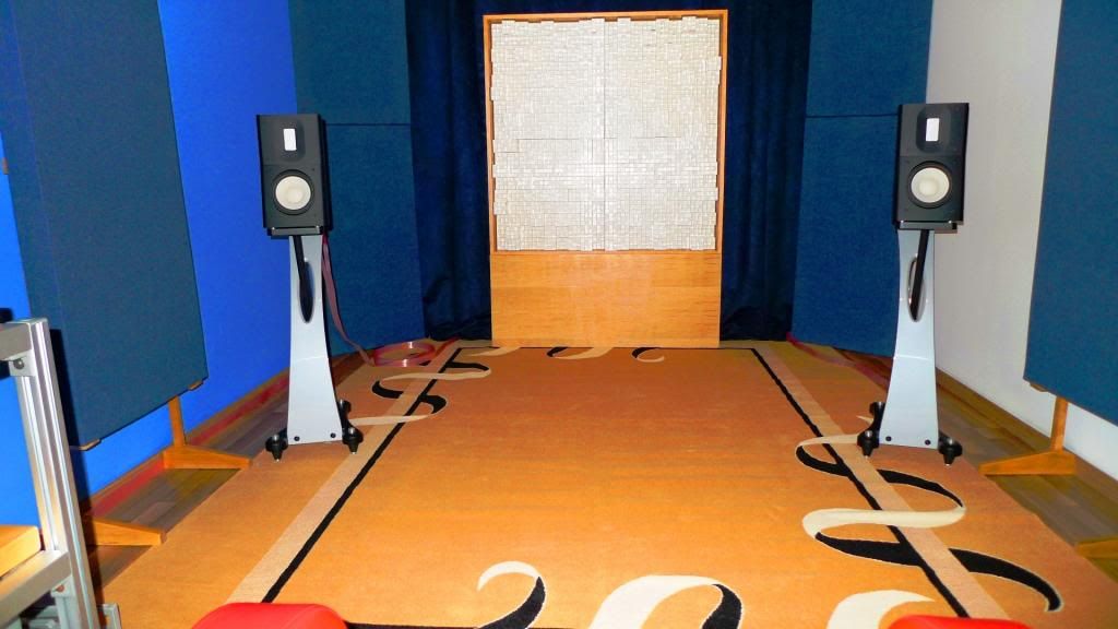
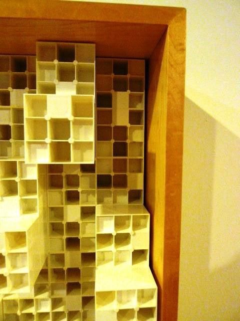
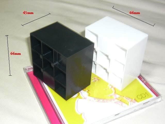
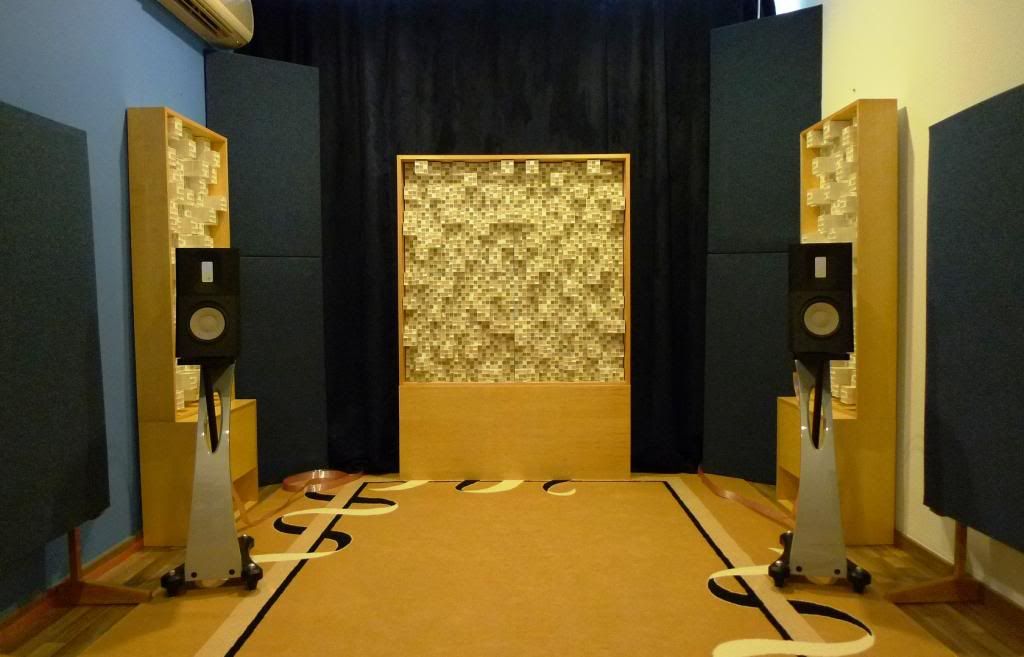
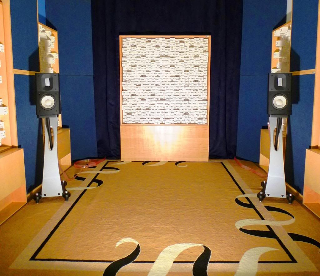
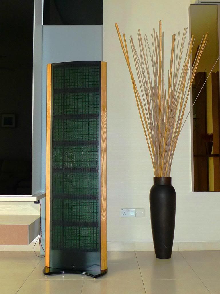
Photo 1: Close up photo of the diffusion panel
REFLECTION vs. ABSORPTION
This was an easy win for Absorption. Versus no treatment, absorption at the first reflection point produced a far superior central image with greater solidarity and focus. Furthermore, not only was there produced soundstage wider and deeper but instrumental localization was light years better. The improved focus also underpinned observations around resolution with micro-details being bought out more from the otherwise cluttered and homogenized mix. Bass too was also improved with far greater control and more realistic decays being observed on good orchestral recordings.
Were there any benefits to not treating the first reflection point? I observed two of note. First, while the central vocal image was more solid with absorption the more diffuse image rendered via reflection came across as more airy and live. Live recordings seemed more alive and more enveloping which with the right software was beneficial. Second, less amplifier power was needed to achieve the same SPL at the seating position. I was very surprised how much absorption attenuates perceptions of loudness or put another way – how much more amplifier power is needed when absorption is introduced.
Overall the benefits of absorption far outweighed those of reflection – though I can understand personal preference will play a role here.
ABSORPTION vs. DIFFUSION
Versus diffusion, absorption at the first reflection point once again produced a better defined central image with marginally better ambience also being noted. However, absorptions benefits seemed to end there because diffusion appeared (strangely) to offer overall better resolution combined with superior air in and around instruments and actors. Despite the benefits absorption created with image – the image observed via diffusion simply seemed more life-like, more real and whilst some dimensionality was lost this did not hinder either the articulation or the comprehension of vocals.
Overall the listening test nod went to the use of diffusion at the first reflection point which admittedly sets me at odds with literature and I dare say to the audiophile thought collective to.
Time then for some more tests….
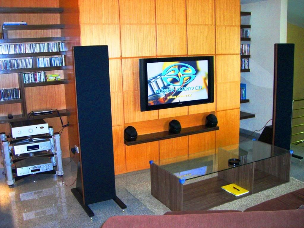
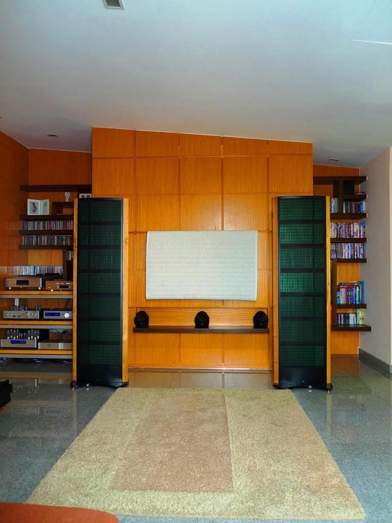
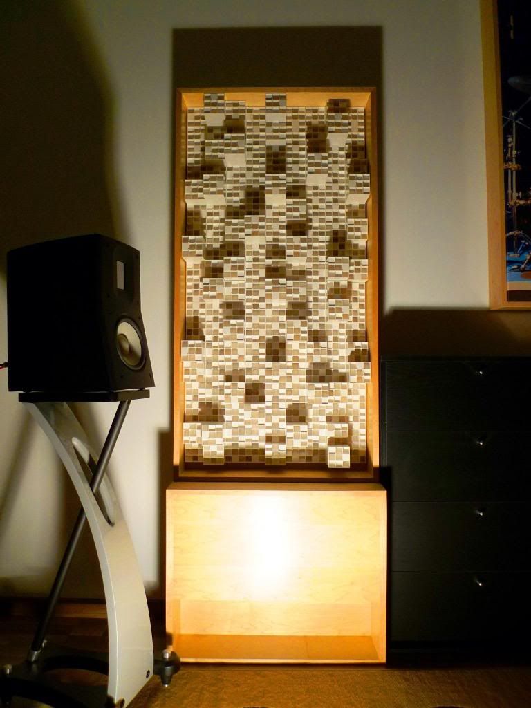
Photo 2: Diffusion panel with bass trap underneath
LEDR TESTS
Like most audiophiles (I’m guessing) I have a quiver full of Test CD’s including those from Stereophile [Test CD2], XLO [Test & Burn in CD], Chesky [Ultimate Demonstration Disc] and Sheffield Labs [The Sheffield / A2TB Test Disc]. The most useful disc to date has been from Nordost via its “System Setup and Tuning Disc”. On this disc Nordost includes what I have come to consider as one of the most enlightening, instructive and valuable of speaker / room interaction tests – LEDR. LEDR™ stands for
Listening Environment Diagnostic Recording, a test to subjectively evaluate the accuracy of stereo image reproduction. LEDR test tones are a series of computer generated tones created by EASI to assess speaker positioning and room interaction.
“Lateral” and “Over” tests can provide valuable insights on important set up questions such as are my speakers correctly spaced apart, positioned and toed and are reflections from side walls or ceilings adversely impacting the image?
Test results showed here that diffusion at the first reflection point created a smoother motion both on lateral and over tests – with the left / right (lateral) in particular having greater symmetry and evenness.
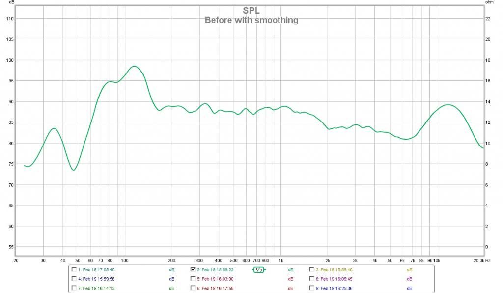
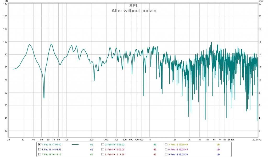
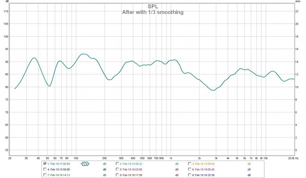
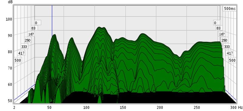
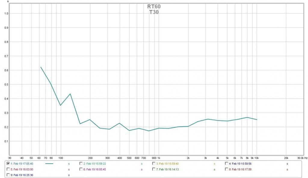
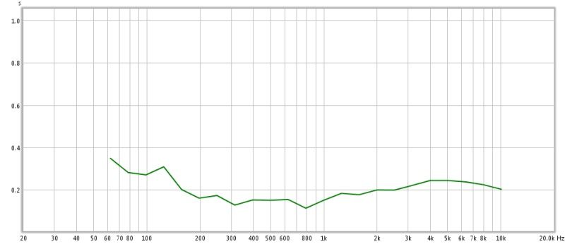
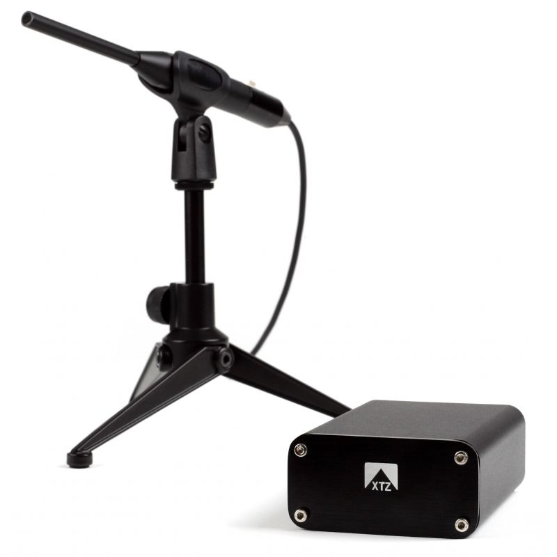
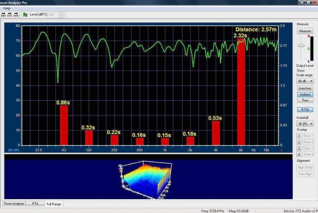
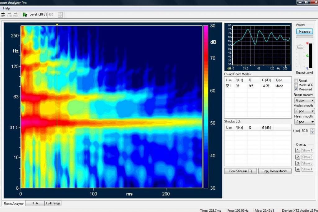
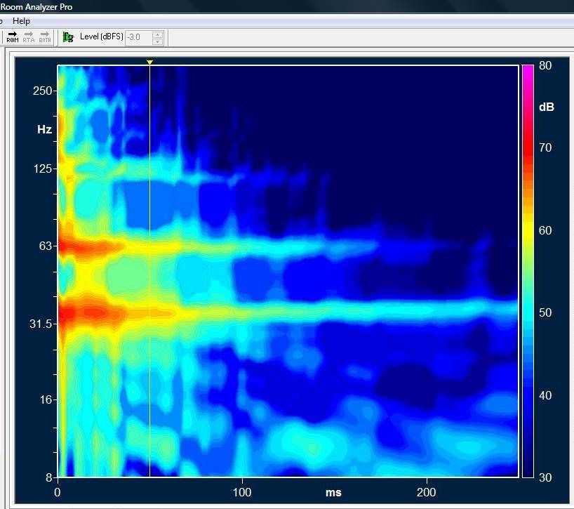
In my next post I will provide some measured results for the room.